SPN 111 - FMI 3 (Fault Codes: CLS Circuit Failed High) - Detroit Diesel Diagnostic Link (DDDL) Software
SPN 111 FMI 3
SPN111 FMI3
CLS - Coolant Level Sensor (DETROIT 60 Series)
 |
| Figure 1.1 - CLS Circuit Failed High (Check Engine) |
Here the STEPS:
1). Connect DETROIT Engine DDEC using Detroit Diesel Diagnostic Link (DDDL v6.50). Read More: How to Connecting DETROIT Engine using Detroit Diesel Diagnostic Link (DDDL).
2). Once connected, open Diagnostics - Fault Codes menu.
 |
| Figure 1.2 - Coolant Level Sensor (Input Voltage High) |
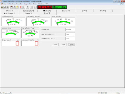
3). Open Diagnostics - Diagnostic Instrumentation or Normal Instrumentation, and monitor the "Coolant Level". When Fault Codes "CLS" is active, "Coolant Level" will displays: No Data. Read More: Diagnostic Instrumentation on Detroit Engine (DDEC) using Detroit Diesel Diagnostic Link (DDDL).
Coolant Level Sensor
 |
| Figure 1.3 - Coolant Level (No Data) |
Coolant Level Sensor
The Coolant Level Sensor (CLS) is required for DDEC IV installations. Its purpose is to provide
an input to the engine protection system and warn the operator if a low coolant level has been
reached.
The main component of the CLS consists of a conductivity probe that connects to the ECM. See Figure 1.4 below.
 |
| Figure 1.4 - CLS Specifications |
The probe should be located in either the radiator top tank or a remote mounted surge tank. It
should be mounted horizontally in the center of the tank, and must be in a position to signal low
coolant before aeration occurs. Typically, this is a height representing 98% of the draw-down
quantity. The probe should be located so that it is not splashed by the de-aeration line, stand pipe
or coolant return line flows. The insulated portion of the probe should be inserted into the coolant
0.5 in. or more past the inside wall of the tank. See Figure 1-5.
 |
| Figure 1.5 - CLS (Top of Radiator Tank) |
#DESCRIPTION OF FLASH CODE 16
Flash Code 16 indicates that the engine Coolant Level Sensor (CLS) input to the ECM has exceeded 95% (normally > 4.75 volts) of the sensor supply voltage.
This diagnostic condition is typically:
- Open sensor signal circuit
- Open sensor ground circuit
PID = P111
FMI = 3
Fault Description = Coolant Level Sensor - Input Voltage High
#TROUBLESHOOTING FLASH CODE 16
1). Sensor Check
Perform the following steps to check the sensor.
1. Turn ignition OFF.
2. Disconnect Coolant Level Sensor (CLS) connector and install a jumper between sockets A and B of the CLS harness connector.
3. Attempt to start and run engine at idle.
4. Read DDR for active codes.
→If active code 111/3 and any other codes except code 111/4 are logged, refer to "Signal Circuit Check".
→If active code 111/4 and any other codes are logged, refer to "Signal Short to Ignition Check".
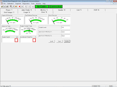
→If no active codes, indicates that wiring are OK. Also check the "Coolant Level" on Diagnostic/Normal Instrumentation will displays: Full.
5. Stop Engine. The problem should on the CLS, replace the sensor.
 |
| Figure 1.6 - Coolant Level (Full) |
2). Signal Circuit Check
Perform the following steps to check the signal circuit.
1. Turn ignition OFF.
2. Disconnect the CLS.
3. Disconnect the vehicle harness connector.
4. Measure resistance between socket H3 (#115) on the vehicle harness connector and A (#115 signal) of the CLS connector.
→If the resistance measurement is less than or equal to 5 ohms, refer to "Ground Circuit Check".
→If the resistance measurement is greater than 5 ohms, or the signal line #115 is open, repair the open.
 |
| Figure 1.7 - CLS and Circuits |
Perform the following steps to check the ground circuit.
1. Measure resistance between cavity B (battery ground) of the CLS connector and battery ground.
→If the resistance measurement is less than or equal to 5 ohms, refer to "Signal Short to Ignition Check".
→If the resistance measurement is greater than 5 ohms, or open, the ground circuit is open. Repair the open.
4). Signal Short to Ignition Check
Perform the following steps to check for a signal short to ignition.
1. Disconnect the vehicle harness connector at the ECM.
2. Remove the jumper wire at the CLS harness connector.
3. Turn ignition ON.
4. Measure voltage at cavity A (#115 signal) of the CLS connector and battery ground. Refer to Figure 1-7.
→If the voltage measurement is less than or equal to 6 volts, refer to "ECM Connectors Check".
→If the voltage measurement is greater than 6 volts, the CLS signal line (#115) is shorted to the 12/24 volt DC line. Repair the short or replace the #115 wire.
5). ECM Connectors Check
Perform the following steps to check the ECM connectors.
1. Inspect terminals at the vehicle harness connector (both the sensor and harness side) for bent, corroded and unseated pins or sockets. Check terminal and pin H3 at the ECM and all terminals and pins in the CLS connector. See Figure 1-8.
→If terminals and connectors are not damaged, replace the CLS.
→If terminals and connectors are damaged, repair both.
#Additional Note:
→Check on Retrieved Calibration - Protection menu. There's settings on Coolant Level (Coolant). Read More: Open and Changing the Customer Calibration using Detroit Diesel Diagnostic Link (DDDL).
a). Warning
b). Rampdown
c). Shutdown
1. Inspect terminals at the vehicle harness connector (both the sensor and harness side) for bent, corroded and unseated pins or sockets. Check terminal and pin H3 at the ECM and all terminals and pins in the CLS connector. See Figure 1-8.
→If terminals and connectors are not damaged, replace the CLS.
→If terminals and connectors are damaged, repair both.
 |
| Figure 1.8 - Vehicle Harness Connector |
#Additional Note:
→Check on Retrieved Calibration - Protection menu. There's settings on Coolant Level (Coolant). Read More: Open and Changing the Customer Calibration using Detroit Diesel Diagnostic Link (DDDL).
a). Warning
b). Rampdown
c). Shutdown
 |
| Figure 1.9 - Coolant Level (Coolant) - Protection |
 |
| Figure 1.10 - Coolant Level (Warning) |
En este caso para hacer una prueba rápida y sin checar la
ReplyDeletecontinuidad de la línea hacia el ecm lo que puedes hacer es quitar el arnés y hacer un puente dado que un extremo del conector va hacia la tierra ya sea en la cabina o el motor y la otra línea va hacia el ecm este si es un sensor on/off y si está dañado puedes hacer un puente y si el software ya no detecta el código puedes operarlo así sin ningún problema yo lo hice y pude cersiorar que realmente era el sensor y no hice extra !!!