HMI (Human Machine Interface)
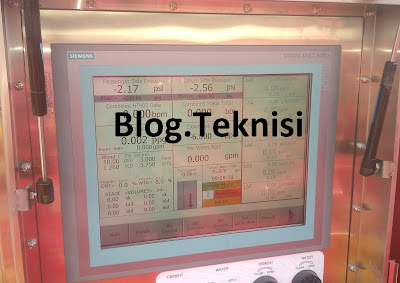 |
| Figure 1.1 - Simatic Multi Panel (Siemens Touchscreen) |
You need to install both "Simatic Step 7" and "WinCC Flexible" Software from Siemens. Today, we'll try to make a connection between PLC S7-300 and your PC or Laptop using "
Ethernet" Port.
Read More:
#Connecting a PG/PC via Industrial Ethernet
1). Make connection: LAN cable (Cat 5) to Ethernet Port (P1 or P2) on PLC S7-300 (CPU317-2 PN/DP) to your PC or Laptop.
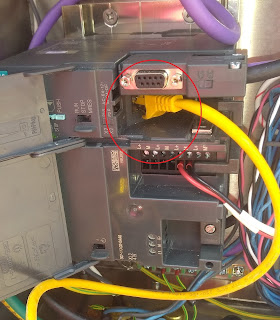 |
| Figure 1.2 - Ethernet Port (P1 or P2) |
2). Open "Simatic Step 7" Software: Options - Set PG/PC Interface... menu.
 |
| Figure 1.3 - Set PG/PC Interface |
3). Make sure: "Ethernet Network Connection.TCPIP.Auto.1" is Active. You can check through Diagnostics.., then click Test button (Results: OK).
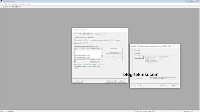 |
Figure 1.4 - Diagnostics (Test) Interface
|
4). Click on Properties... - Network Properties button to set IP address on your PC or Laptop. All PROFINET devices use the TCP/IP protocol. For this reason, they need IP address when operated on the Ethernet.
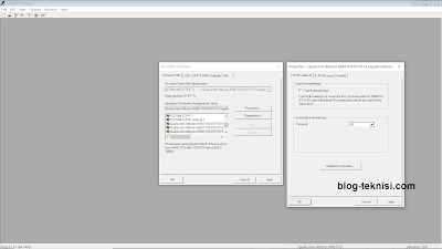 |
Figure 1.5 - Network Properties
|
5). On Local Area Connection: double click - Properties - Internet Protocol Version 4 TCP/IPv4, and set your IP address and Subnet mask, then click OK.
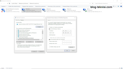 |
Figure 1.6 - IP address and Subnet mask
|
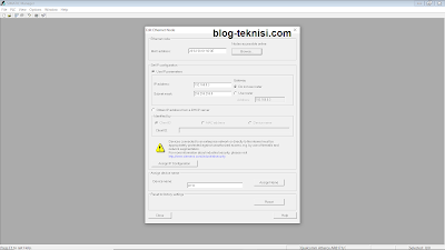
6). Next: Go to PLC - Edit Ethernet Node... menu.
 |
| Figure 1.7 - PLC (Edit Ethernet Node...) |
7). Click Browse... it will automatically searching (or click Start button) the IP address for the PLC S7-300. Once done, click OK.
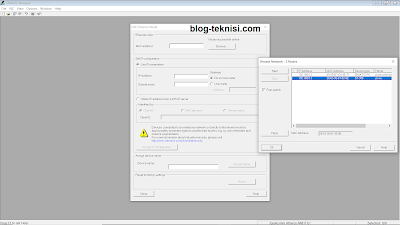 |
Figure 1.8 - Browse Network (PLC - IP address)
|
 |
| Figure 1.9 - Click Close |
8). If we look at the configuration in HWI Config (Ethernet Address Assignment), to configure an Ethernet you must assign a MAC address or IP address to the Ethernet interface.
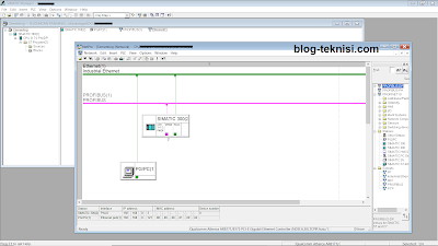 |
| Figure 2.1 - Ethernet Address Assignment |
#Set a HMI Display1). Open "WinCC Flexible" Software, click on Project - Retrieve... menu. Then load/choose your WinCC Flexible RT document.
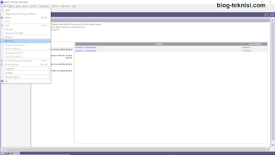 |
Figure 2.2 - Project (Retrieve...)
|
 |
| Figure 2.3 - Open PROJECT_1.hmi |
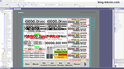 |
Figure 2.4 - Start Screen
|
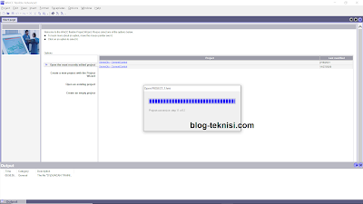
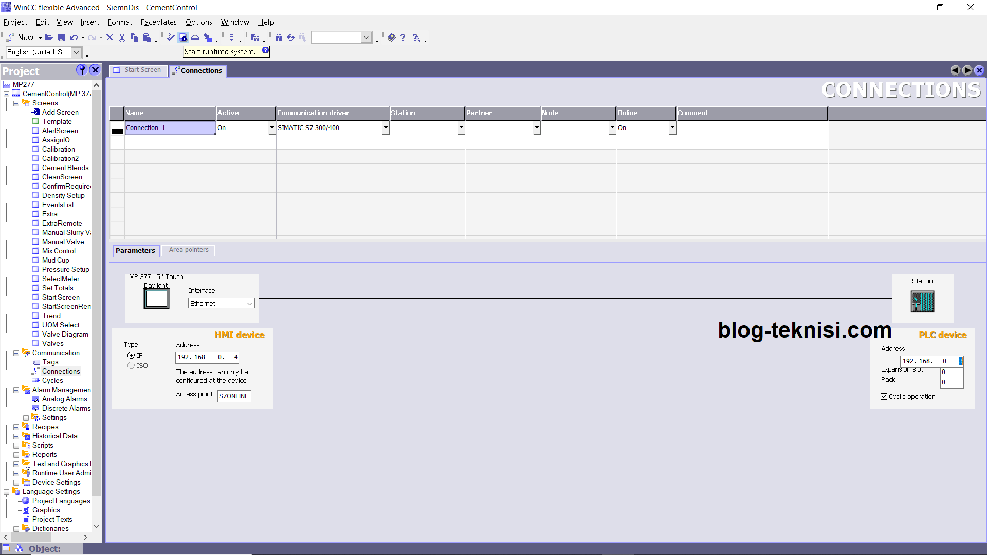
2). Set the Communication using Ethernet (Interface), input both IP address your PC or Laptop (HMI device) and the PLC/Station (PLC device). Then click Start runtime system, wait until the Output compiler is finished.
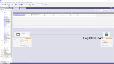 |
| Figure 2.5 - Ethernet (Interface) |
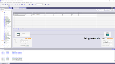 |
Figure 2.6 - Compiling finished
|
3). If the connection is correct, a HMI Display on your PC or Laptop should appears as your "Simatic Multi Panel" (as Figure 1.1 above).
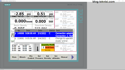 |
Figure 2.7 - HMI Display on PC/Laptop (correct)
|
4). If the connection is failed, a HMI Display on your PC or Laptop will displays the "#####" values.
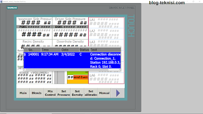 |
Figure 2.8 - HMI Display on PC/Laptop (failed)
|


This comment has been removed by the author.
ReplyDelete