Allison 3000/4000 Product Families - Torque Converter
Torque Converter - Fleets
The Torque Converter is located at the front of the Transmission, and acts as a fluid coupling to transfer torque from the Engine
to the Transmission gearing.
The Torque Converter:
- Uses rotational output from the Engine to create rotational input to
the Transmission
- Acts as a clutch to engage and disengage input into the Transmission
- Can increase the amount of Engine-created torque that is delivered
to the Transmission gearing
During Engine idle, the fluid coupling provides separation
between the Engine and Transmission so that the Engine doesn’t stall.
- When the vehicle is stopped and Engine rpm is increased, the Torque Converter multiplies Engine torque and transfers that torque to the Transmission gearbox
- When the appropriate conditions are sensed, the lockup clutch is applied to provide a direct, mechanical connection between the Engine and Transmission
A). Torque Converter Components
Key torque converter components include the:
- Pump
- Stator
- Turbine
- Lockup clutch
The Torque Converter pump is physically connected to and
driven by the Engine.
- The converter hub drives the Transmission charging pump
The Torque Converter turbine provides torque converter
output to the Transmission turbine shaft.
- Splines in the converter turbine hub engage the splines on the turbine shaft
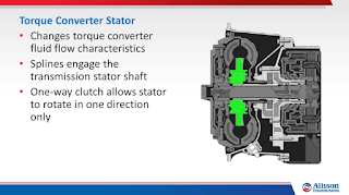
- The stator splines engage the transmission stator shaft (sometimes
referred to as the "ground sleeve")
- A one-way clutch allows the stator to rotate in one direction only
- The stator is stopped (or "locked") when the converter is creating
or multiplying torque (referred to as Vortex Flow)
- The stator rotates once the vehicle is moving and torque multiplication stops (referred to as Rotary Flow)
The Transmission turbine shaft provides the primary input
from the Engine to the Transmission gears.
- Splines on the turbine shaft engage splines in the torque converter
turbine hub
The Transmission stator shaft is a non-rotating, stationary
shaft anchored in the Transmission front support assembly.
- Stator shaft splines engage splines in the torque converter stator
to enable the stator one-way clutch operation
The lockup clutch provides a direct mechanical drive from
the Engine to the Transmission gearing, and consists of three elements:
- The piston, which is driven by the Engine
- The backplate, which is driven by the Engine
- The clutch plate/damper assembly, which is located between the
piston and the backplate, and splined to the converter turbine
B). General Operating Theory
The Torque Converter housing is filled with fluid.
- Fluid leaving the turbine is directed to the stator
- During Vortex Flow, the stator is locked and redirects this fluid
back to the pump, aiding pump rotation and multiplying torque provided to
the Transmission
- During Rotary Flow, the stator freewheels, eliminating the assist
provided to the torque converter turbine; the pump, turbine, stator and
fluid inside the torque converter all rotate together
Pump, stator and turbine vane size and shape affect torque
converter performance characteristics, including Stall Torque Ratio.
- Stall Torque Ratio indicates the maximum amount of torque multiplication
created when the converter is “stalled” (when the pump is rotating and the
turbine is stationary)
- Stall Torque Ratio is expressed numerically – for example, a 2:1
Stall Torque Ratio converter can double Engine torque


0 Response to "Allison 3000/4000 Product Families - Torque Converter"
Post a Comment