FREE Caterpillar ET Software: Programming Engine Cooling Fan for On-Highway Trucks
Engine Cooling Fan
 |
| Figure 1.1 - Cooling Fan Drive and Clutch (C13 Truck) |
(A). Accessing the Configuration on CAT ET software - Input Selections and Output Selections:
1). Fan Control Type
The Fan Control Type parameter determines if the ECM is used to operate the Engine Cooling Fan, this parameter must be programmed to "On/Off", to "Three-Speed Fan", or to "Variable Speed Fan Option S". This parameter must be programmed to "None" if the ECM is not operating the Cooling Fan relay or the Cooling Fan Solenoid.
 |
| Figure 1.2 - Fan Control Type |
#Alternatives:
→None
→On/Off PWM
→On/Off DC
→Three-Speed Fan PWM
→Three-Speed Fan DC
→Variable Speed Fan Option S
#Advantages:
When the Engine ECM controls the Engine Cooling Fan, there is no need for second set of Coolant Temperature Sensors. Engine ECM fan control also provides additional features, such as Fan with Engine Retarder in High Mode.
 |
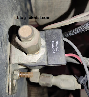
| Figure 1.3 - Engine Fan Clutch Solenoid |
2). Fan Override Switch
The Fan Override Switch parameter is programmed to identify the Fan Override Switch connection to the ECM. This parameter can be programmed to one of the available hard-wired options or J1939 data-link source inputs. The switch itself allows the Operator to turn on the Cooling Fan at any time, resulting in improved retarding/braking and Engine cooling.
#Alternatives:
→None
→J1/P1:7 (Input 4)
→J1/P1:47 (Input 5)
→J1/P1:6 (Input 6)
→J1/P1:46 (Input 7)
→J1939 - Body Controller
→J1939 - Cab Controller
→J1939 - Instrument Cluster
#Advantages:
When programmed to one of the input Alternatives, this parameter allows the use of the Fan Override Switch, which results in improved Engine retarding/braking and Engine cooling.
 |
| Figure 1.5 - Engine Fan Auto/Manual Switch |
(B). Accessing Diagnostic Tests from the Diagnostic menu, and then select Special Tests from
the submenu. Click Start.
 |
| Figure 1.6 - Special Tests |
 |
| Figure 1.7 - On/Off Cooling Fan - J1/P1:11 (Not Active) |
→Check the Engine Fan Clutch Solenoid should be activated now.
 |
| Figure 1.8 - On/Off Cooling Fan - J1/P1:11 (Active) |
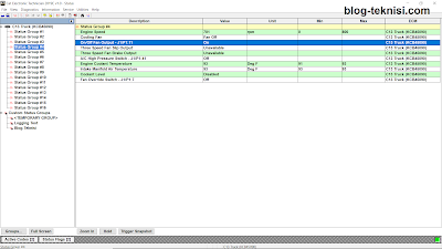
(C). Accessing the Status Tool to check the circuit for the Engine Cooling Fan:
#Key switch ON
→Cooling Fan = Fan On
→On/Off Fan Output - J1/P1:11 = Off
→Engine Coolant Temperature = 91 Deg F
→Fan Override Switch - J1/P1:7 = Off
#Starts the Engine (Idle Speed) - Engine Fan Auto/Manual Switch OFF (to Auto Mode)
 |
| Figure 2.1 - Engine Run (Idle Speed) |
→Engine Speed = 701 rpm
→Cooling Fan = Fan Off → Disengaged
→On/Off Fan Output - J1/P1:11 = On
→Engine Coolant Temperature = 93 Deg F
→Fan Override Switch - J1/P1:7 = Off
#Engine Run (Idle Speed) - Engine Fan Auto/Manual Switch ON (to Manual Mode)
 |
| Figure 2.2 - Fan Override Switch (On) |
→Engine Speed = 701 rpm
→Cooling Fan = Fan On → Engaged
→On/Off Fan Output - J1/P1:11 = Off
→Engine Coolant Temperature = 95 Deg F
→Fan Override Switch - J1/P1:7 = On
#Engine Run (Idle Speed) - Engine Fan Auto/Manual Switch OFF (to Auto Mode) - Simulate the Engine Coolant Temperature (above 200 Deg F)
 |
| Figure 2.3 - Engine Coolant Temperature (230 Deg F) |
→Engine Speed = 699 rpm
→Cooling Fan = Fan On → Engaged
→On/Off Fan Output - J1/P1:11 = Off
→Engine Coolant Temperature = 187-230 Deg F
→Fan Override Switch - J1/P1:7 = Off
Read More:
Blog.Teknisi


This article provides a clear and concise explanation of how to control an engine cooling fan using Arduino and a temperature sensor. The step-by-step instructions and code examples make it easy to follow, even for those with limited programming experience.
ReplyDeleteI particularly appreciate the emphasis on the practical application of this project. Controlling the engine cooling fan is an important task for maintaining a vehicle's engine temperature, and this article provides a practical solution using readily available components.
Tips: Visit https://www.chipsmall.com/ to learn more info about components.