Software Configuration: Fracturing Transmission TH55
Transmission TH55-E70/E90
 |
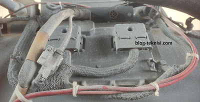
| Figure 1.1 - ECM Transmission TH55 |
1). ECM Identification Parameters
a. Equipment ID - Text description of application (17 characters).
b. Transmission Serial Number - Text entry of Transmission Serial Number (PCJXXXXX).
c. Torque Converter Serial Number - This parameter sets the Torque Converter Serial Number. The Serial Number prefix is used to enable the appropriate Torque Converter software parameters, depending on which Torque Converter (TC6400) is installed in the Transmission (TC6400 S/N Prefix: T2H).
2). System Settings
a. Transmission Configuration Code - This parameter specifies Transmission application (7025).
b. Lockup Clutch Disengagement Engine Speed - This value sets the automatic lockup disengagement speed based on Engine performance to prevent shift hunting (Cat3512 B/C/E - 1300 rpm).
c. Flywheel Teeth - This parameter sets the number of Engine flywheel teeth (Cat3512 B/C/E - 151).
d. Engine Reference Torque Override Configuration - This parameter sets the peak Engine torque N-m (lb ft) for Engines that do not broadcast reference torque over J1939 (Cat3512 B/C/E - 10027 N-m/ 7396 lb ft ).
e. Engine Control Datalink Configuration - This parameter indicates the data link the Engine communications over (J1939).
f. Transmission High Temperature Neutralization Enable Status - This parameter, if enabled, shifts the Transmission into a "safe mode" NEUTRAL condition in an overheating event (Disabled).
 |
| Figure 1.2 - Configuration (Fracturing Transmission) |
3). Shifter #1
a. Transmission Shifter #1 Input Configuration - Sets type of communications used by the shifter (CAN Input).
b. Transmission Shifter #1 Minimum Forward Gear - The Transmission will not shift below this gear when Shifter #1 is active (1).
c. Transmission Shifter #1 Maximum Forward Gear - The Transmission will not shift above this gear when shifter #1 is active (7-9).
4). Shifter #2
a. Transmission Shifter #2 Input Configuration - Sets type of communications used by the shifter (CAN Input).
b. Transmission Shifter #2 Minimum Forward Gear - The Transmission will not shift below this gear when Shifter #1 is active (1).
c. Transmission Shifter #2 Maximum Forward Gear - The Transmission will not shift above this gear when shifter #1 is active (7-9).
5). Input Selections
a. Lockup Clutch Disable Feature Installation Status - This feature allows the use of a switch to disable LUC engagement for continuous converter drive operation (Installed).
b. Transmission Neutral Request Park Break Enable Status - This parameter enables a Neutral delete feature and will shift the Transmission to PARK when NEUTRAL is requested.
c. Low Flow Transmission Control Desired Speed Input Configuration - This parameter is for DTOC functionality.
d. Low Flow Transmission Control Input Configuration - This parameter is for DTOC functionality.
e. Engine Torque Correction Factor - This parameter is for DTOC functionality.
f. Engine Driven Accessory Load Configuration - This parameter is for DTOC functionality.
g. Low Flow Transmission Control Installation Status - This parameter is for DTOC functionality.
Note: DTOC (Dynamic Transmission Output Control)
Read More:
Blog.Teknisi
Great! I learned about the Transmission TH55-E70/E90.
ReplyDelete