Cylinder Cutout/ Injector Test
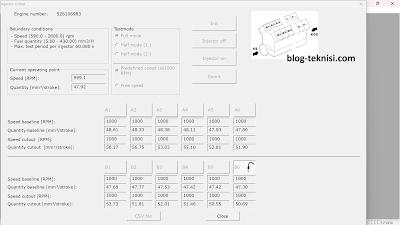 |
| Figure 1.1 - Cylinder Cutout (ECU-7) |
If the Cylinder Cutout is active, the Engine governor will activate only one half of the Injectors alternately. The Cylinder Cutout is active in Predefined Speed (1000 RPM) and Free Speed. It guarantees Engine operation free of white smoke.
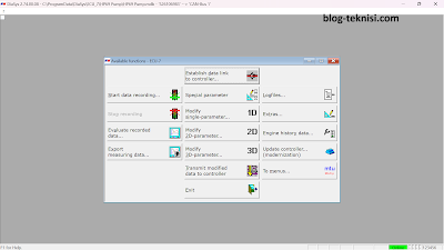 |
| Figure 1.2 - Available functions (ECU-7) |
2). Select Extras...
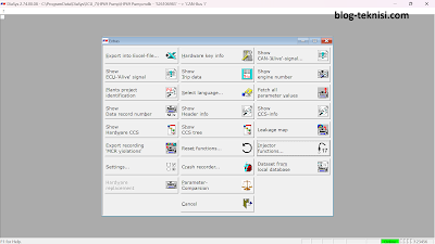 |
| Figure 1.3 - Extras |
3). Select
Injector functions...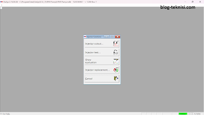 |
| Figure 1.4 - Injector functions |
#Injector Cutout
4). Select
Injector cutout...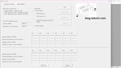 |
| Figure 1.5 - Injector cutout |
→Select Testmode (Full mode/ Half mode 1/ Half mode 2) and Engine Speed (Predefined/ Free Speed).
→Select Init
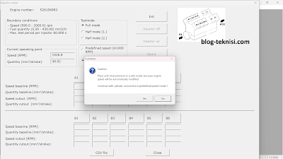 |
| Figure 1.6 - Common/Caution |
→Select
Yes on Common (Caution) message box.
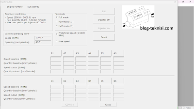 |
| Figure 1.7 - Injector off |
→Select the Injector (A1-A6, and B1-B6), then select
Injector off button.
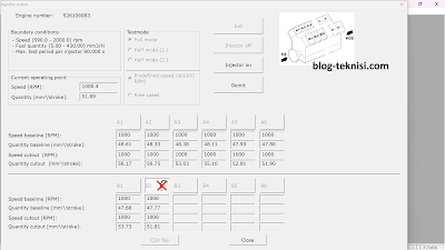 |
| Figure 1.8 - Injector on |
→Select
Injector on button when finished, and change to another Injector.
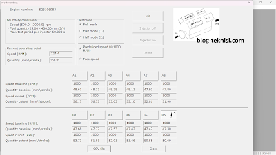 |
| Figure 1.9 - Injector cutout (Deinit) |
→After all Injector cutout completed, select
Deinit button.
→Select CSV file to see the results on .csv file
→Select Close to close the test.
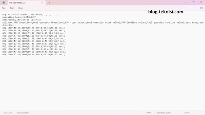 |
| Figure 2.1 - CSV file |
#Injector Test5). Select Injector test...
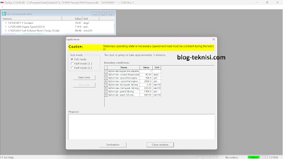 |
| Figure 2.2 - Injector test |
→Select
Test mode (Full mode/ Half mode 1/ Half mode 2), then select
Start test button. It will automatically start the Injector test from A1 until B6.
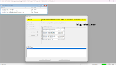 |
| Figure 2.3 - Injector test (Test started) |
→Select Stop test to stop the test.
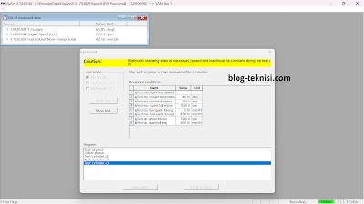 |
| Figure 2.4 - Test Cylinder A3 |
→Please wait until all Injector test is finished.
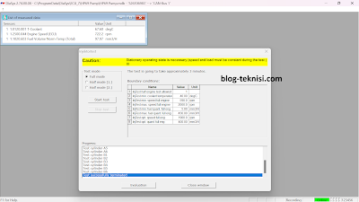 |
| Figure 2.5 - Test successfully terminated |
→Select Evaluation to see the results.
→Select
Print or
Export the file.
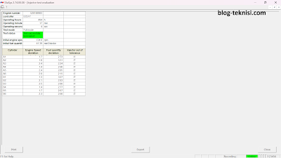 |
| Figure 2.6 - Injector test evaluation |


Source Traceability & Cost Saving
ReplyDelete